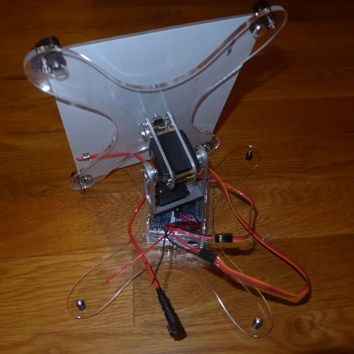
Solar Tracker
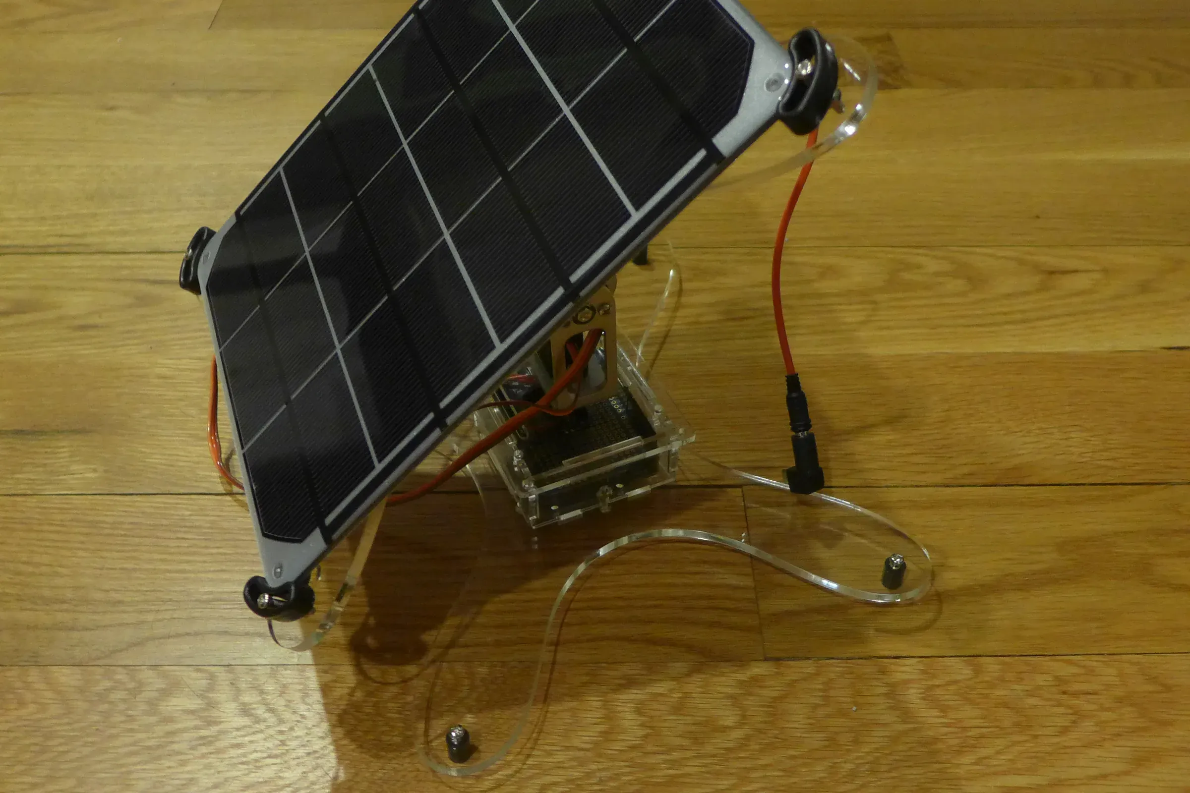
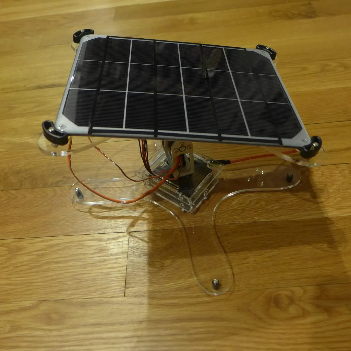
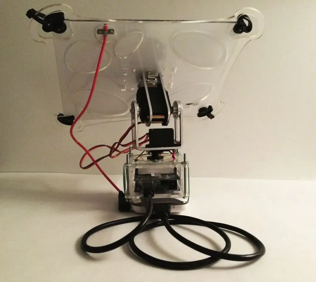
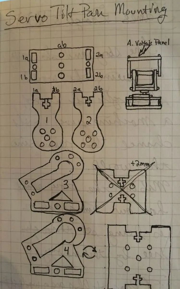
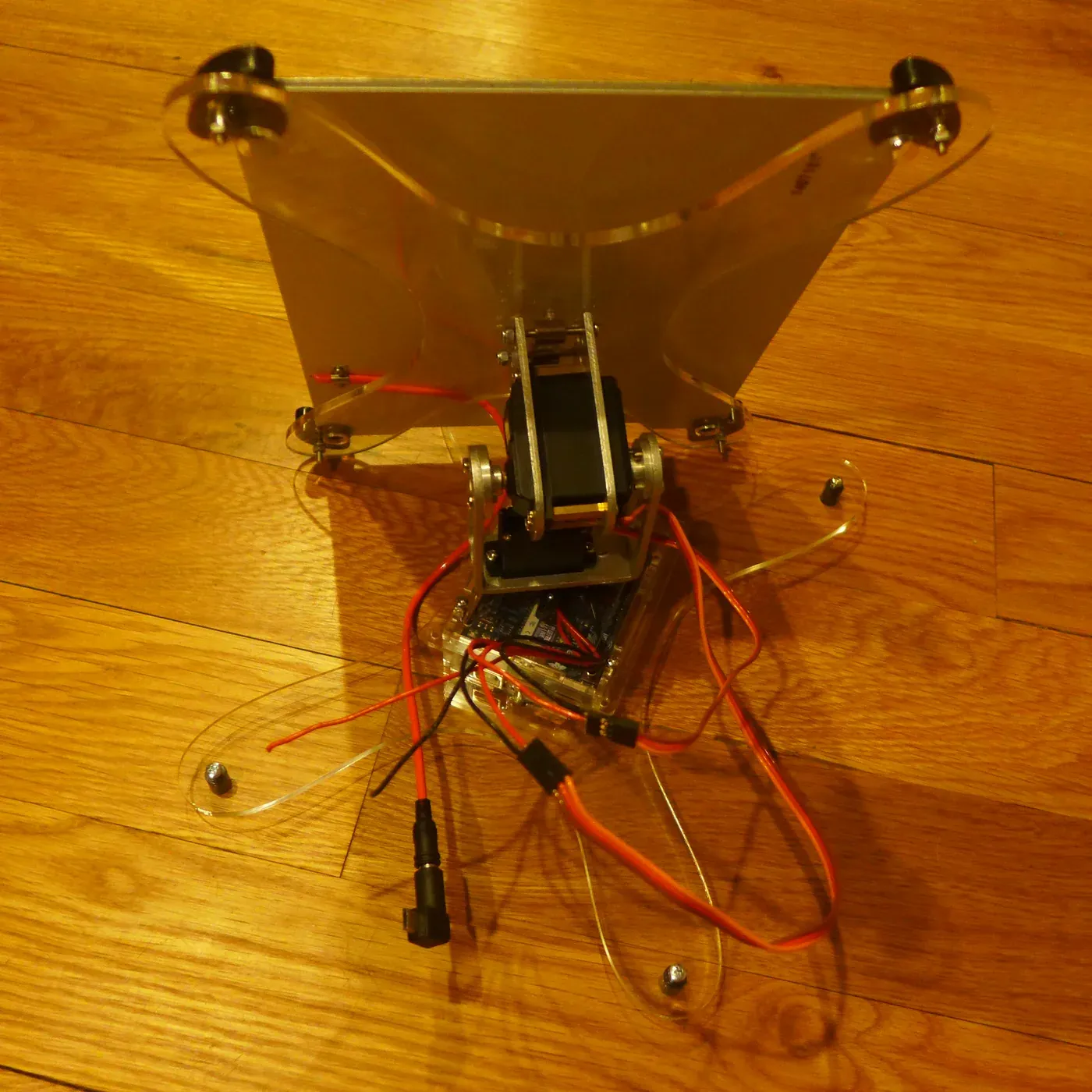
In November 2014 I started drawing a mount for a small Voltaic solar panel. The parts were an Arduino, two hobby servos, one to turn and one to tilt, and flat sheets of clear acrylic for everything else.
Two versions
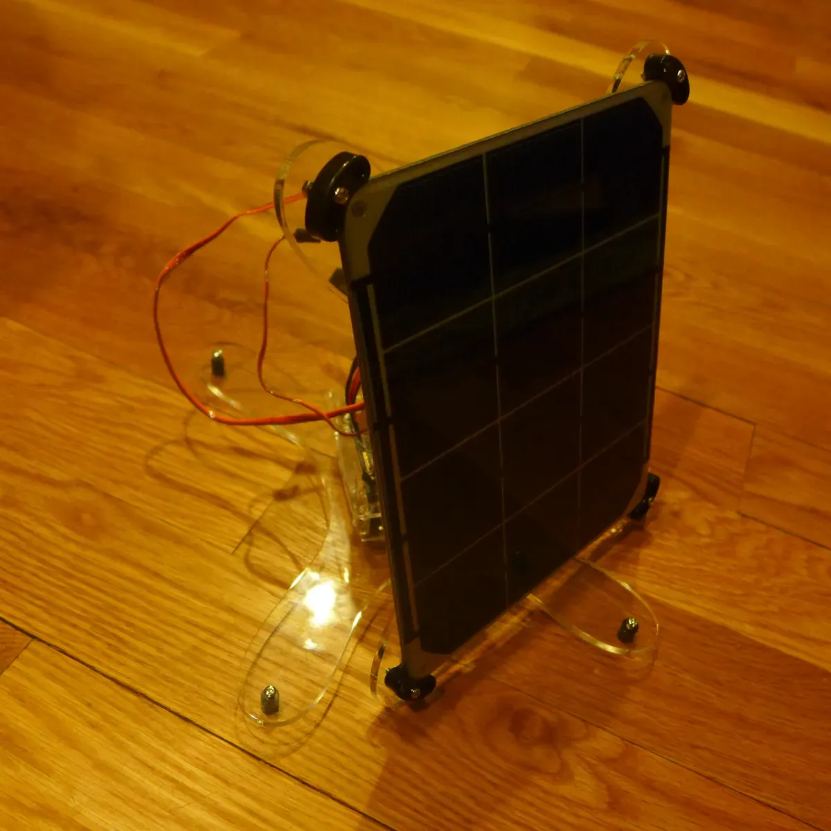
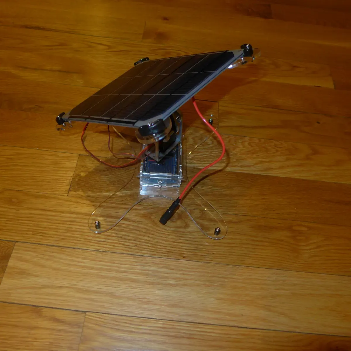
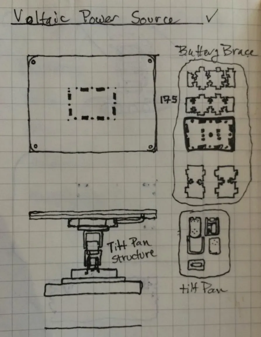
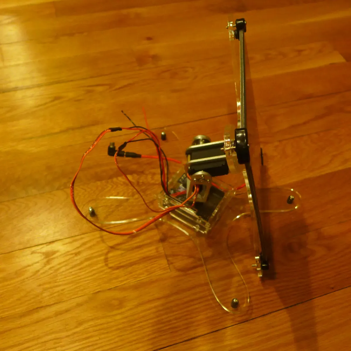
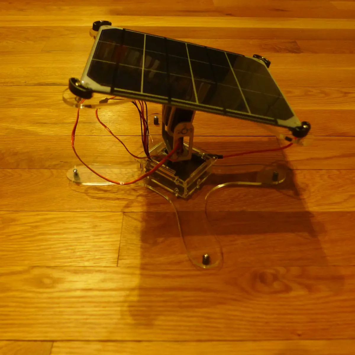
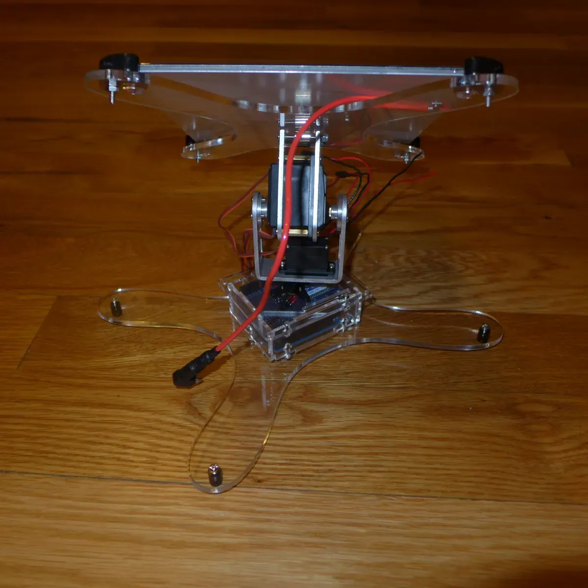
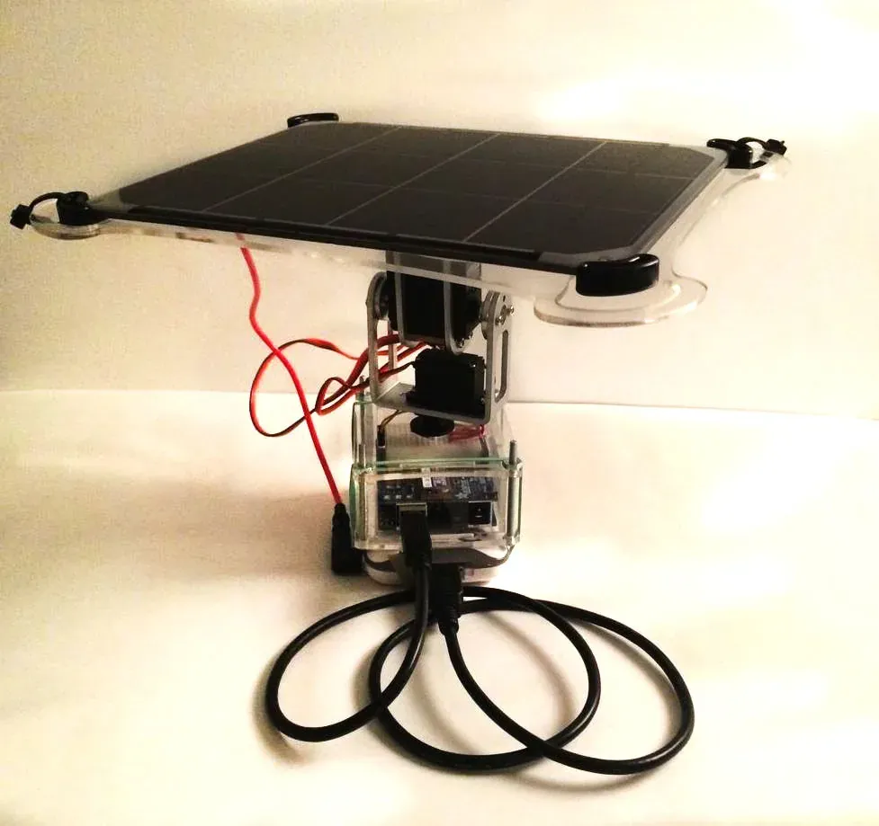
The first drawings are dated 8 November 2014. Within a week the files had become a tracker: a pan and tilt bracket under the panel, and a clear acrylic case for the board. Photographs from 24 November show it built.
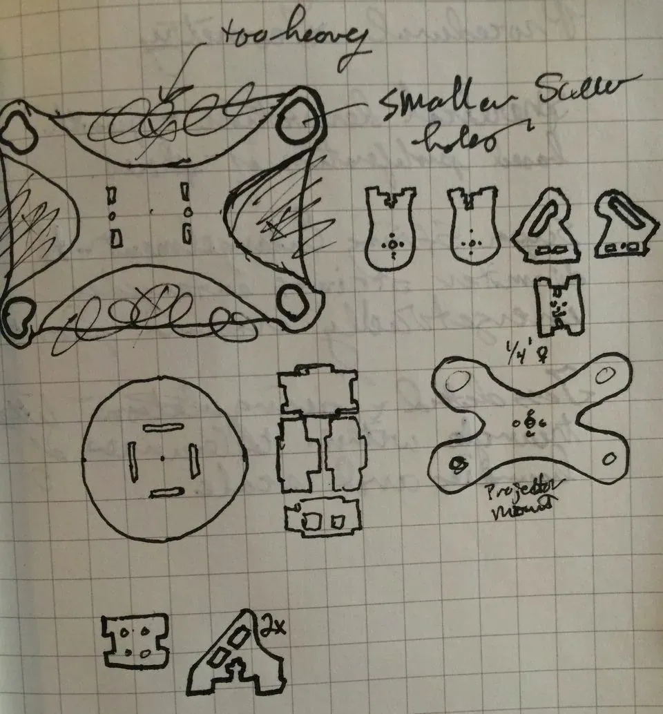
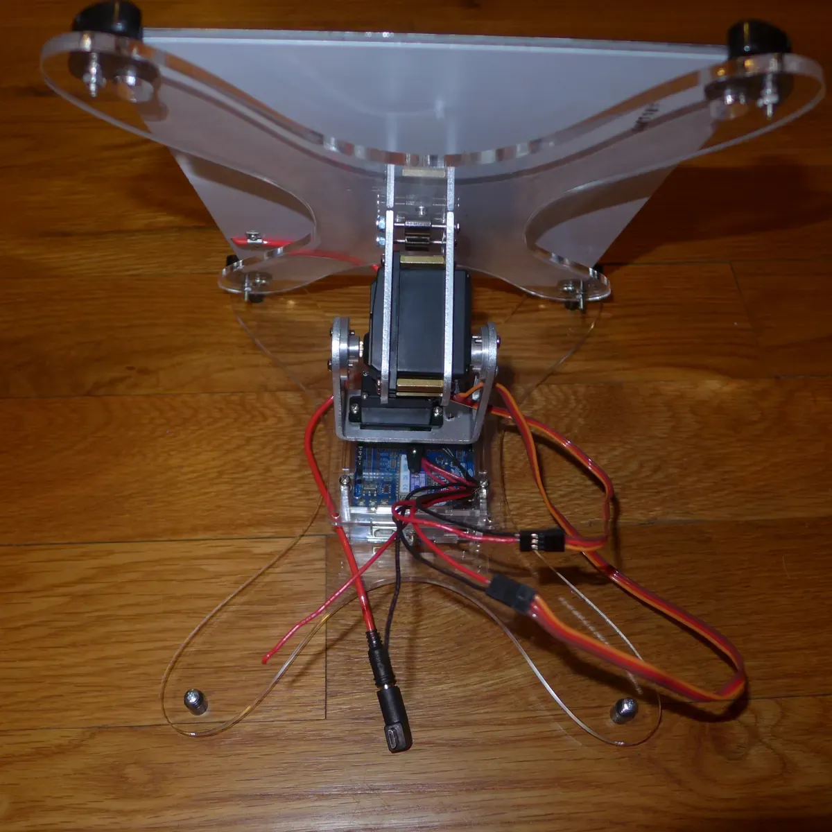
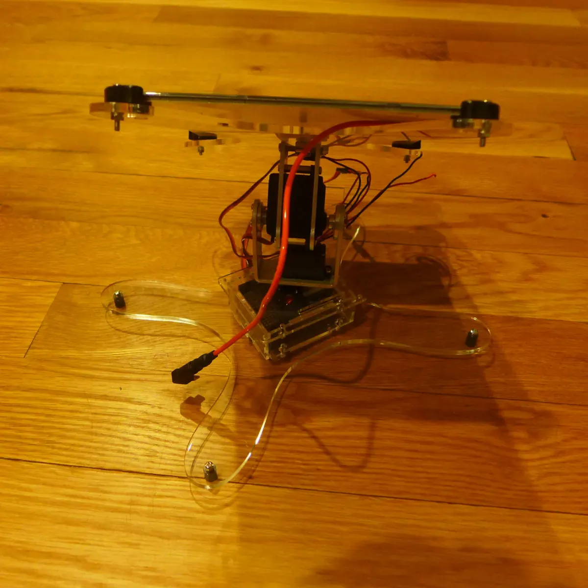
In early April 2015 I redrew it as one set of laser-cut parts: a frame for the panel, four looping legs, and the two servos stacked in the middle. I photographed that version on 4 April 2015.
The missing loop
The code never closed the loop. One sketch sweeps a servo back and forth through its range. Another, from January 2015, reads an accelerometer, an ambient light sensor and a hydrogen sensor, and prints the numbers. Nothing in the files connects the light reading to the servos. The panel could move and the board could see light, but I have no record of it following the sun.
From the notebook
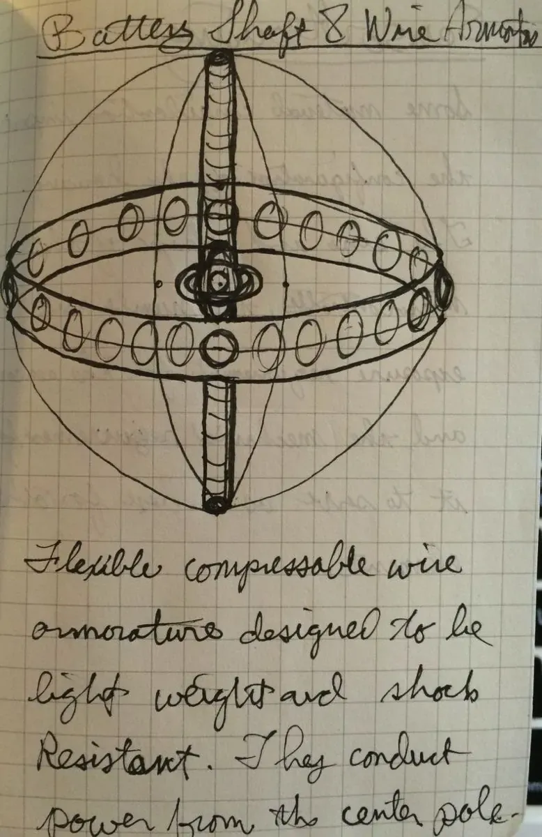
A notebook page from the same month, written about a walking robot: “3D printed components are ideal, however a cheaper faster laser cut approach is better for prototyping.”
More photographs and notebook pages, 2014–15